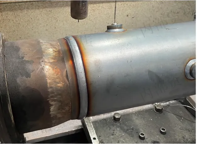
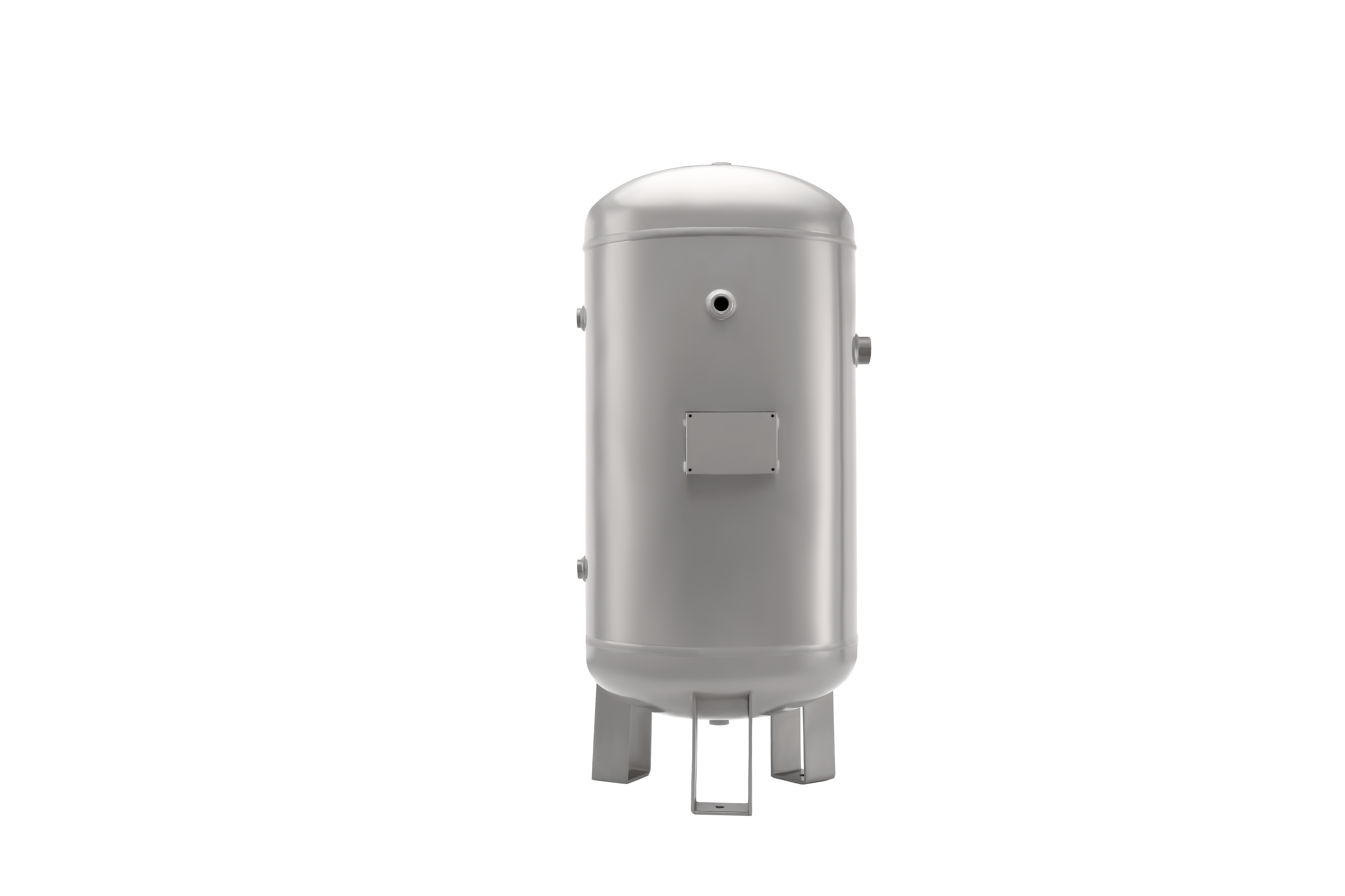
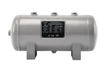
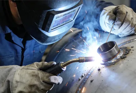
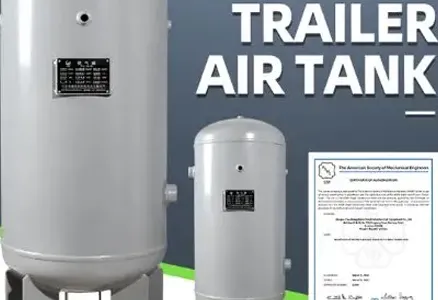
The circumferential girth seam forms the primary pressure‑bearing joint that connects the body and end caps of industrial air receivers. As the most critical weld on an entire pressure vessel, its structural integrity directly determines the tank’s pressure‑withstanding capacity, fatigue performance and overall operational safety under repeated cyclic pressure loading. Defects such as porosity, slag inclusion, misalignment, burn‑through and hot cracks on girth seams may remain hidden beneath the surface. Over extended service cycles, these flaws can propagate into major cracks, leading to gas leakage or even catastrophic tank rupture.
Many air tank manufacturers rely heavily on post‑weld non‑destructive testing to catch welding defects. However, inspection alone cannot fix quality problems created by poor preparation. Unverified raw materials, dirty tooling, loose fixtures, incorrect shielding‑gas ratios, mis‑calibrated welding parameters or poorly maintained torch components will produce avoidable weld imperfections, raising rejection rates, rework costs and production lead‑times. At YCZX, we implement a complete seven‑step standardized automatic girth‑seam welding workflow. Quality control is embedded throughout the whole process, starting from drawing validation, tooling maintenance, gas configuration, torch upkeep, parameter fine‑tuning all the way to post‑weld visual assessment. Every procedure follows formal work instructions, minimizing defects before welding commences. This rigorous process ensures that our girth welds satisfy GB150, ASME Section VIII Div.1 and global pressure‑vessel standards, delivering safe and durable air receivers for worldwide industrial customers.
Step 1: Drawing and workpiece verification
Before commencing girth‑seam welding, operators cross‑reference physical components against technical drawings. Key attributes including shell thickness, outer diameter, material grade and weld position are carefully verified. This step prevents material mix‑ups and dimensional errors that would result in non‑compliant pressure‑vessel assemblies. Per YCZX workshop regulations, welding is strictly forbidden if material or dimensional specifications deviate from drawing requirements. Any distorted cylinder shell must be fully calibrated and corrected before tack‑welding and fit‑up. Only qualified pre‑assembled workpieces are allowed to enter the automatic welding station.
Step 2: Tooling mould cleaning
Residual welding slag accumulated inside clamping moulds can scratch and damage the surface of dished heads during positioning. Operators manually knock out trapped slag debris and apply protective oil on mould surfaces. Safety rules specify that slag removal may only take place after welds cool down to ambient temperature; chipping hot weld metal is prohibited. If previous weld defects are observed, operators mark defect locations clearly before removing slag. Thorough mould cleaning protects workpiece surfaces and eliminates foreign‑body sources for new welds.
Step 3: Mould fixture inspection and tightening
Loose clamping moulds are a frequent source of weld misalignment and slag entrapment. Operators shake mould assemblies by hand to detect clearance and slack, then retighten all fasteners with wrenches. Fixture inspection is mandatory before every welding cycle, and re‑checks are required even mid‑batch. Clamping force must be precisely balanced. Over‑loose fixtures cause joint offset and slag inclusion; over‑tight clamping squeezes and permanently deforms cylinder shells. Proper fixture tension maintains consistent butt‑joint alignment throughout automatic welding.
Step 4: Shielding‑gas mixture parameter confirmation
Consistent gas protection is essential for stable girth‑seam quality. YCZX adopts a certified mixed‑gas formula of 85 % argon and 15 % carbon dioxide for girth‑seam production. Operators validate gas pressure and flow settings against the approved WPS (Welding Procedure Specification). Excess pressure and flow create turbulent airflow that induces weld porosity. Insufficient gas supply fails to form an inert protective envelope, resulting in oxidized weld beads with degraded mechanical properties. Prior to arc start, gas pipelines are fully purged to expel trapped atmospheric air, avoiding contamination of the initial weld passes.
Step 5: Apply anti‑clogging agent to welding torch nozzle
With power disconnected and the torch fully cooled, operators apply a thin layer of anti‑clogging compound to the nozzle inner wall and contact tip front end. Application is restricted exclusively to gas‑passage zones. Conductive contact surfaces must be kept clean; excess anti‑clogging agent is wiped away completely. This maintenance practice reduces spatter adhesion, prevents nozzle blockage and sustains stable gas delivery during long‑run automatic welding production.
Step 6: Welding‑parameter adjustment and setting
Two groups of standard welding parameters are defined for YCZX automatic girth‑seam equipment: Set 1: 29 V voltage, 340 A current; Set 2: 28 V voltage, 335 A current. The automatic travel speed is set at 10.29 m/min. Operators carry out short trial weld segments to observe molten‑pool behaviour and fine‑tune parameters. Cylinder rotation speed must synchronize accurately with torch travel speed.
Current and voltage must remain well‑matched. Mismatched settings such as high current with low voltage cause wire explosion, while high voltage paired with low current produces unstable wandering arcs. Current output is appropriately reduced at arc‑start, arc‑stop and transition corners to prevent burn‑through and surface pits. Contact tips are replaced every working day, and protective shrouds are cleaned of spatter daily. The welding torch is held at a 45‑degree working angle with optimized stand‑off height to guarantee full shielding‑gas coverage over the entire girth‑seam zone.
Step 7: Post‑weld visual inspection of circumferential weld
After welding completion, operators pause machine operation and perform comprehensive visual inspection over the full circumference of the girth seam. Key evaluation items include weld reinforcement, bead width consistency, joint misalignment and complete groove fusion. Inspection can only begin once the workpiece has cooled to ambient temperature, to avoid thermal burns and missed detection of hot cracking. Special attention is paid to inner‑seam blind spots together with arc‑initiation and arc‑termination zones. Workpieces showing non‑conforming appearance are clearly marked for rework. Units with defective welds cannot flow to downstream manufacturing stages. If fit‑up gap or misalignment exceeds permissible tolerance, welding is prohibited and mechanical correction must be performed first.
High‑quality circumferential welds cannot be achieved by equipment performance alone. They depend on systematic multi‑layer process control: drawing validation, tooling cleaning and tightening, shielding‑gas calibration, torch maintenance, precise parameter tuning and careful post‑weld visual screening. YCZX does not rely solely on later‑stage non‑destructive testing to discover hidden flaws. Instead, we embed quality gates at every production stage to stop defects from being generated in the first place.
This automatic welding procedure connects upstream tack‑welding processes and downstream grinding, non‑destructive testing and air‑pressure leak testing. It constitutes a core component of YCZX’s closed‑loop quality‑management system for pressure vessels. Every production step follows documented work instructions and retains process traceability. By eliminating risks stemming from wrong materials, poorly maintained tooling, gas deviation and improper welding settings, we effectively lower defect rates and rework overhead. For global industrial partners across machinery manufacturing, compressed‑air systems, mining and energy sectors, YCZX delivers code‑compliant air receivers with robust main pressure‑bearing welds, consistent build quality and dependable long‑term operational safety.