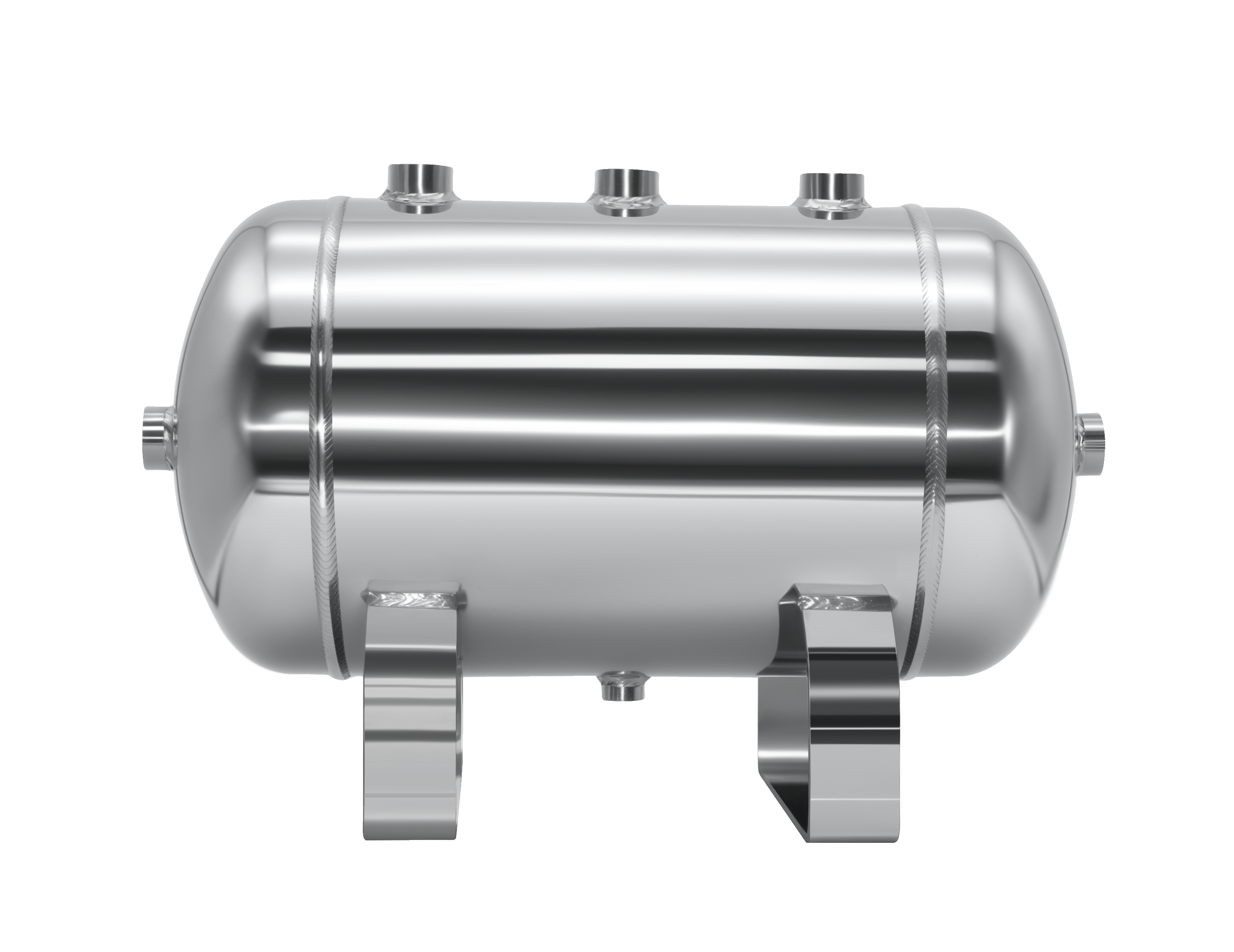
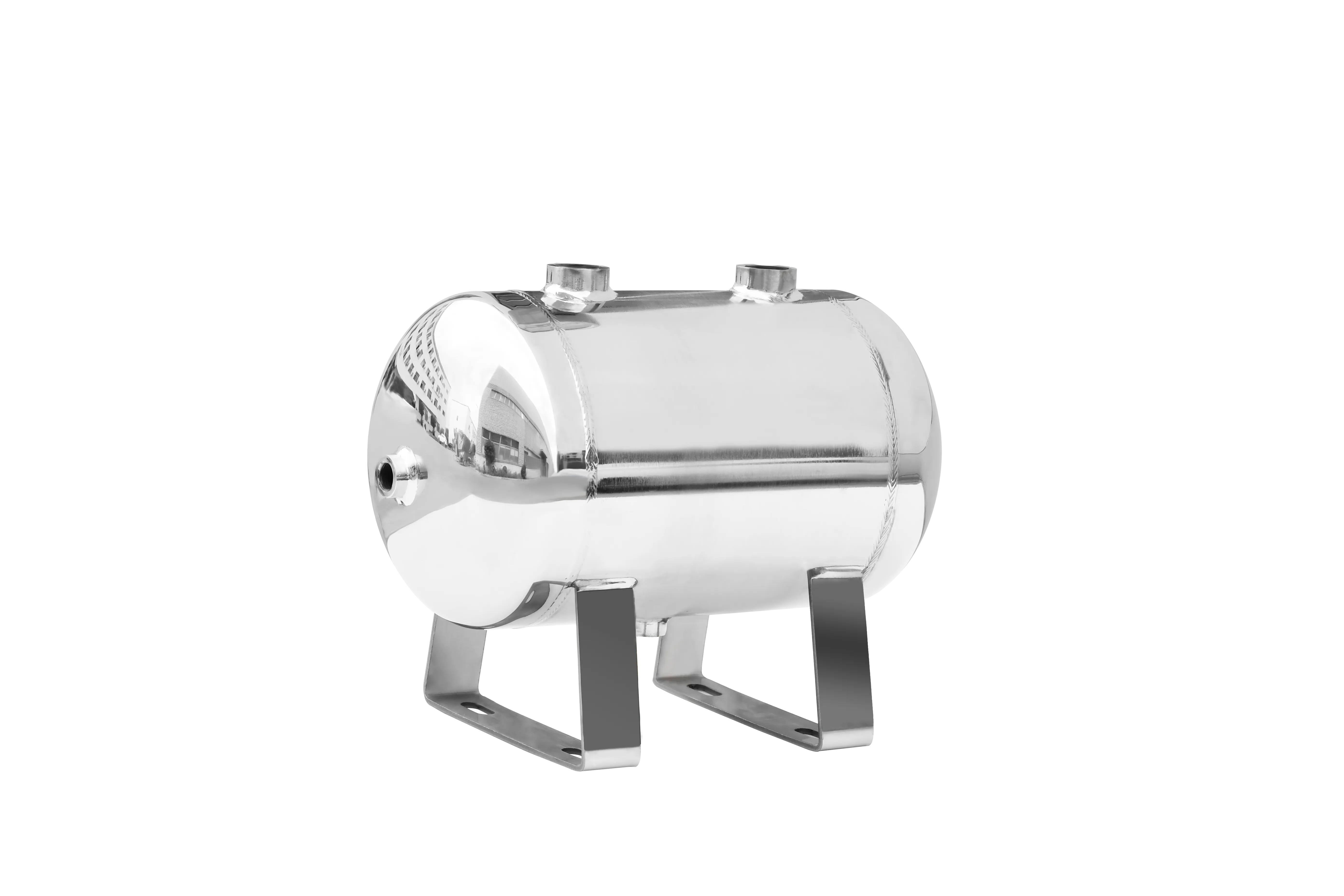
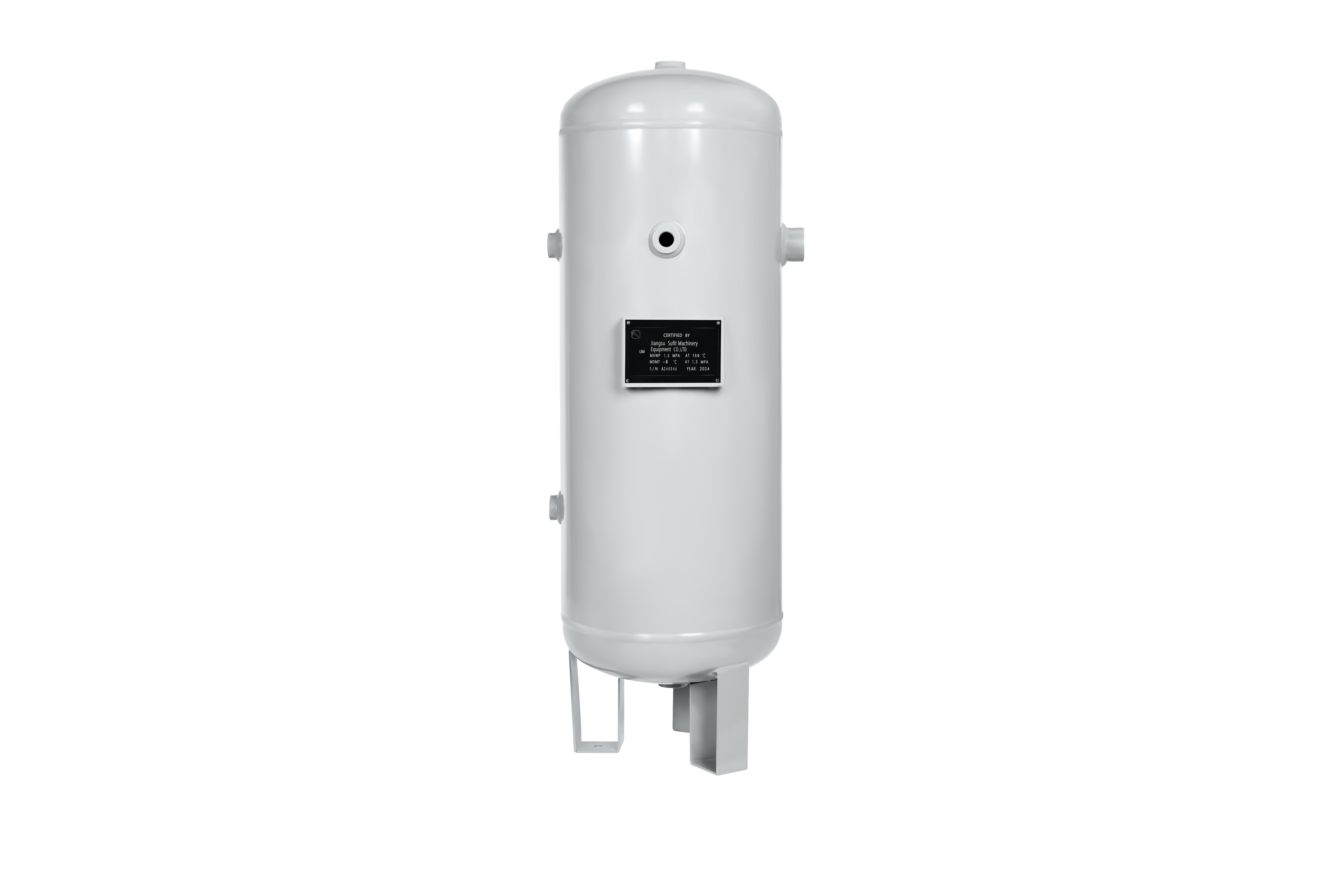
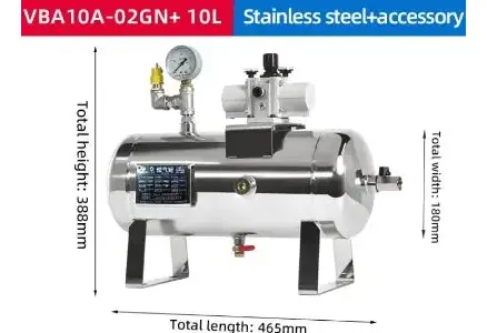
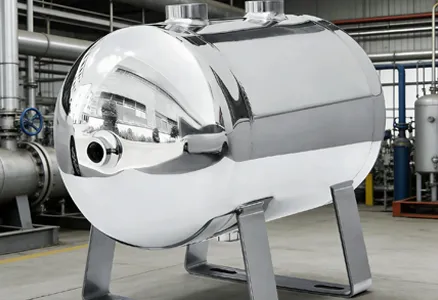
Support brackets (foot stands) are critical load‑bearing structural components for industrial air receivers. These welded supports carry the full dead‑weight of the pressure vessel, sustain static gravity loads as well as minor dynamic vibration generated during compressor cycling. Poor bracket welding will trigger a series of practical problems: uneven installation height, tilted tank placement, weld cracking under long‑term load, and even detachment of support feet. Any failure of support‑bracket joints will compromise overall equipment stability and may introduce secondary stress onto the main pressure‑bearing shell of the air receiver.
Many air receiver manufacturers treat support‑bracket welding as a non‑critical secondary welding task. Operated without dedicated fixtures and standardized process specifications, bracket position, spacing and verticality vary widely among finished units. Thermal distortion from improper welding creates hidden risks of bracket‑joint fracture under long‑term service. At YCZX, we regard support‑stand welding as a vital part of pressure‑vessel quality assurance. Our standardized four‑step workflow covers drawing verification, fixture positioning, tack‑welding fixation and multi‑layer fill welding. Special tooling guarantees consistent dimensional accuracy across production batches. Strict welding‑heat control reduces thermal deformation, and visual inspection intercepts surface defects. This process ensures robust support‑bracket connections, matches GB150 and international pressure‑vessel requirements, and delivers stable, reliable air receivers for global industrial‑sector clients.
Step 1: Drawing verification and pre‑weld preparation
Before welding operations commence, operators cross‑check physical workpiece dimensions against technical drawings. Correct custom‑built fixtures are selected for the corresponding product model, and anti‑spatter oil is applied onto fixture surfaces. Anti‑spatter oil prevents welding spatter from adhering to tooling surfaces, maintaining fixture precision and simplifying post‑process cleaning.
Operators confirm that physical workpieces fully comply with drawing specifications. Each support‑bracket component is inspected for cracks, twists or other material defects. Only defect‑free brackets can enter assembly. After temporary tack‑welding is completed in early positioning stages, all welding slag must be thoroughly removed before moving to formal welding. This preliminary check eliminates non‑conforming raw parts at the source and avoids wasting production time on defective components.
Step 2: Work‑piece positioning with dedicated fixtures
Dedicated tooling fixtures are the foundation for consistent bracket‑mounting dimensions. Operators place the air‑receiver cylinder shell onto the fixture base and lock positioning blocks securely. Support‑bracket mounting points are precisely aligned. Operators double‑check horizontal level and bracket‑to‑bracket spacing to ensure dimensional conformity before tack‑welding and full‑fillet welding.
Two important workshop rules are enforced. Tack‑welding is strictly prohibited if fixtures are not fully clamped. Unlocked clamping allows components to shift during welding thermal expansion, resulting in positional offset and inconsistent dimensions. Operators are forbidden to force‑bend or press workpieces with brute force for correction. Heavy mechanical force will permanently deform the tank cylinder or support brackets, introducing residual internal stress that weakens long‑term load‑bearing performance. Reliable fixture clamping guarantees repeatable positioning for mass‑produced air receivers.
Step 3: Tack‑welding for bracket fixation
With brackets properly seated by fixtures, operators re‑verify bracket spacing and vertical alignment. Symmetrical two‑point tack‑welding is performed first, completing four positioning tack‑spots in total. Tack‑weld beads are kept short yet mechanically solid. Once tack‑welding is finished, operators re‑measure key dimensions to confirm no positional drift has occurred before proceeding to continuous fill welding.
Parameter control for tack‑welding is highly significant. Tack‑welding current must be kept relatively low. Excessive current risks burn‑through of the cylinder shell and thermal deformation of support feet. Concentrated single‑point tack‑welding is not permitted. Localized heat input at one single spot will twist brackets and cause tilting misalignment. After tack‑welding, surface quality is inspected. Porosity, undercut and weld overlap on tack spots are rejected. Any non‑conforming tack weld must be ground off and re‑positioned. Good tack‑weld quality locks bracket geometry and prepares workpieces for subsequent fillet‑weld filling.
Step 4: Multi‑layer fillet‑weld gap filling
This step completes full fillet joints between support brackets and the air‑receiver shell, achieving fully filled, robust weld beads. Operators manipulate the welding torch with small‑amplitude weaving motion. Weld metal is deposited in multiple layers. Slight dwell time is applied on both sides of the joint, while the torch travels steadily through the central section of the weld groove. Layer‑by‑layer deposition avoids excessive single‑pass weld thickness.
Two core process constraints prevent typical fillet‑weld defects. First, segmented symmetrical welding sequences are adopted. Welding alternates from one side to the opposite side of the bracket set. Distributed heat input effectively minimizes overall thermal distortion of both brackets and cylinder shell. Second, operators are forbidden to deposit overly thick weld metal within one single pass. One‑time heavy build‑up easily traps slag inside welds and generates subsurface porosity. Layered welding allows slag to float out between passes and improves internal weld integrity. Well‑formed fillet welds provide sufficient shear strength to sustain long‑term static weight and operational vibration loads.
Support‑bracket welding may appear as secondary structural work, yet it directly affects installation stability and long‑term service reliability of the whole air receiver tank. Superior bracket joints cannot be achieved by manual experience alone. They rely on systematic process control: drawing‑based pre‑weld validation, precision fixture clamping, low‑heat symmetrical tack‑welding and controlled multi‑layer segmented fillet welding.
YCZX refuses to treat support‑stand fabrication as a low‑priority auxiliary process. Every step follows documented work‑instruction standards. This welding procedure connects upstream shell fabrication and downstream grinding, surface coating and final pallet‑packaging processes. Together with raw‑material inspection, main girth‑seam welding, nozzle welding, non‑destructive examination and air‑pressure leak testing, it forms YCZX’s complete closed‑loop quality‑control system for pressure vessels.
By controlling dimensional accuracy, limiting welding thermal deformation and eliminating common weld defects, YCZX effectively reduces hidden risks such as bracket tilting, joint cracking and shell secondary stress. For worldwide industrial customers engaged in machinery production, compressed‑air stations, mining equipment and general manufacturing, YCZX delivers fully‑compliant air receivers with stable load‑bearing support structures, consistent workmanship and long‑term operational safety.