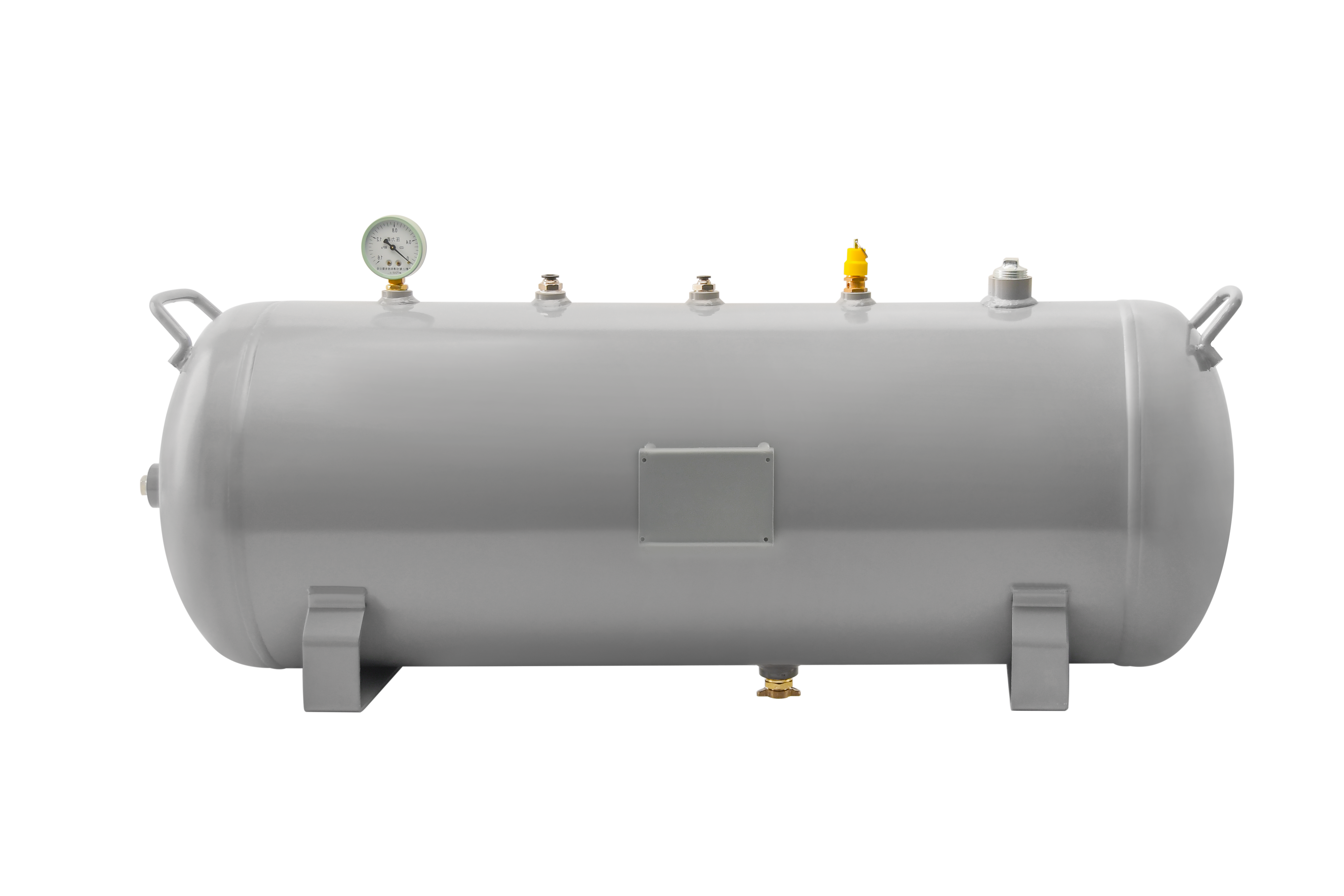
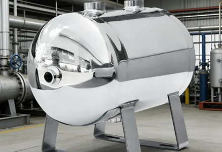
Assembly and tack‑welding is the core intermediate manufacturing stage that joins rolled air tank body and end cap to form the basic closed‑body structure of industrial and custom pressure vessel air receivers. The fit‑up quality between tank body and end cap directly determines circumferential‑girth‑weld performance. Poor alignment, excessive joint misalignment, uneven root gap, or residual welding slag will lead to severe welding‑related hazards such as incomplete fusion, slag inclusion, stress concentration and hidden crack risks, which cannot be fully offset even by high‑performance automatic girth‑welding equipment. Under long‑term cyclic internal‑pressure service, these assembly‑originated defects may propagate into fatigue cracks and threaten overall vessel safety.
Many pressure vessel manufacturers underestimate assembly‑phase quality control. They treat body‑head matching as simple manual positioning, ignoring drawing verification, proper slag‑chipping discipline and standardized symmetrical tack‑welding rules. Improper hammer striking on hot work‑pieces or excessive tack‑weld penetration may produce cold cracks, local denting and thin‑plate burn‑through, creating latent safety risks inside finished tanks. For custom‑built pressure vessels with varied wall‑thicknesses, diameters and head geometries, consistent fit‑up discipline is particularly critical. At YCZX, we implement a complete standardized 3‑step workflow for body head assembly and tack‑welding. Starting from drawing‑and‑material cross‑checking, through head‑to‑shell matching and controlled slag removal, to qualified symmetrical tack‑welding, every step follows documented work‑instructions. This upstream‑quality‑gate mechanism ensures proper pre‑conditions for subsequent automatic girth‑seam welding, and complies with GB150, ASME Section VIII Div.1 pressure‑vessel‑code requirements, delivering robust custom‑engineered pressure vessels for worldwide industrial‑sector customers.
Step 1: Drawing and raw‑material verification before assembly
Before physical assembly operations begin, operators carefully cross‑reference each cylindrical‑shell workpiece against technical drawings. Critical parameters including shell wall thickness, outer diameter, material grade and circumferential‑weld position are fully validated. This verification eliminates material‑mix‑up and dimensional‑deviation risks at the very beginning of assembly.
Strict workshop regulations are enforced. Any shell workpiece whose material grade or dimensional specification deviates from drawing requirements must not enter welding procedures. Deformed cylindrical shells need full calibration and correction before head fit‑up and tack‑welding are permitted. For custom‑order tanks with non‑standard dimensions or special‑grade steel, every single shell is inspected individually rather than relying on batch‑production assumptions. Thorough drawing‑and‑part confirmation prevents unqualified blanks from flowing into subsequent value‑adding welding stations and wasting manufacturing resources.
Step 2: Fit‑up dished heads and controlled slag removal
Operators position dished heads onto both open ends of the cylindrical shell body to complete shell‑head butt joint alignment. After preliminary positioning, chipping hammers are used to remove burrs, residual mill‑scale and temporary‑weld slag along the circumferential‑joint zone. Operators strike at an approximate 45‑degree angle on both sides of the weld groove. Special care is taken for curved‑knuckle and transition‑corner zones of dished heads, where hammer blows must be applied gently.
Two vital operational constraints protect base‑metal integrity. Hammer chipping is strictly forbidden on still‑hot work‑pieces. Impact force applied onto high‑temperature steel may induce cold‑crack initiation inside the heat‑affected zone, severely degrading local mechanical performance. In addition, thin‑walled curved knuckle sections of dished heads receive only light tapping. Heavy striking will create permanent surface dents and local‑wall‑thinning damage on the head. Proper controlled chipping removes surface contaminants that would otherwise cause slag inclusions during formal girth welding, while preserving the original geometry and material integrity of thin‑form dished heads.
Step 3: Circumferential‑joint tack‑welding for groove fixation and gap‑misalignment control
After shell‑head fit‑up and surface cleaning are completed, tack‑welding is performed to temporarily lock dished‑head position, fix butt‑groove geometry, and control joint‑gap and misalignment values within allowable‑code tolerances. Operators place multiple equally‑spaced tack‑weld spots around the full circumference, adopting a symmetrical‑alternating welding sequence from opposite positions around the joint. Symmetrical distributed heat input counteracts uneven thermal shrinkage and minimizes assembly‑joint shifting during tack‑weld solidification.
Multiple key quality‑control rules govern this positioning‑welding phase. Tack‑weld penetration depth must remain moderate. Excessive penetration will burn through thin‑walled dished‑head material and create irreversible base‑metal damage. All slag generated from each tack spot must be completely chipped away. Trapped tack‑weld slag will become embedded as internal slag‑inclusion defects once covered by the subsequent formal girth‑weld passes. Most importantly, if measured joint misalignment or root‑gap exceeds permitted tolerances, welding is totally prohibited. Operators must perform mechanical readjustment and re‑calibration before attempting any tack‑welding.
Properly executed symmetrical tack‑weld spots maintain concentricity between shell and dished‑head, preserve uniform circumferential‑root‑gap, and prevent component shifting during tank rotation inside automatic girth‑welding equipment. It builds stable geometric pre‑conditions for high‑quality full‑penetration girth‑seam welding.
High‑quality pressure‑vessel girth welds are determined long before formal automatic‑welding arcs ignite. Rigorous drawing‑material validation, careful shell‑head fit‑up, temperature‑controlled slag‑chipping and standardized symmetrical tack‑welding jointly define assembly‑joint quality. Assembly‑phase defects such as misalignment, cold cracks, dents and trapped slag cannot be fully repaired in later welding or inspection stages.
YCZX does not treat shell‑head assembly as a simple manual‑fitting task. Every operation follows formal documented work‑instructions. This assembly‑and‑tack‑welding procedure links upstream plate‑rolling processes and downstream automatic girth‑seam welding, nozzle welding, grinding, non‑destructive‑testing, hydrostatic‑testing and final export‑packaging workflows. Together with incoming‑material inspection and every subsequent process step, it constitutes YCZX’s complete closed‑loop quality‑management‑system for custom pressure‑vessel manufacturing.
By enforcing multi‑level quality gates during shell‑head assembly, YCZX minimizes assembly‑induced welding‑defect risks and rework rates. For global industrial partners across general machinery, compressed‑air‑station infrastructure, mining‑equipment and heavy‑industry sectors, YCZX delivers code‑compliant custom‑built air receivers with well‑aligned circumferential joints, consistent weld‑quality and dependable long‑term pressure‑bearing‑safety.