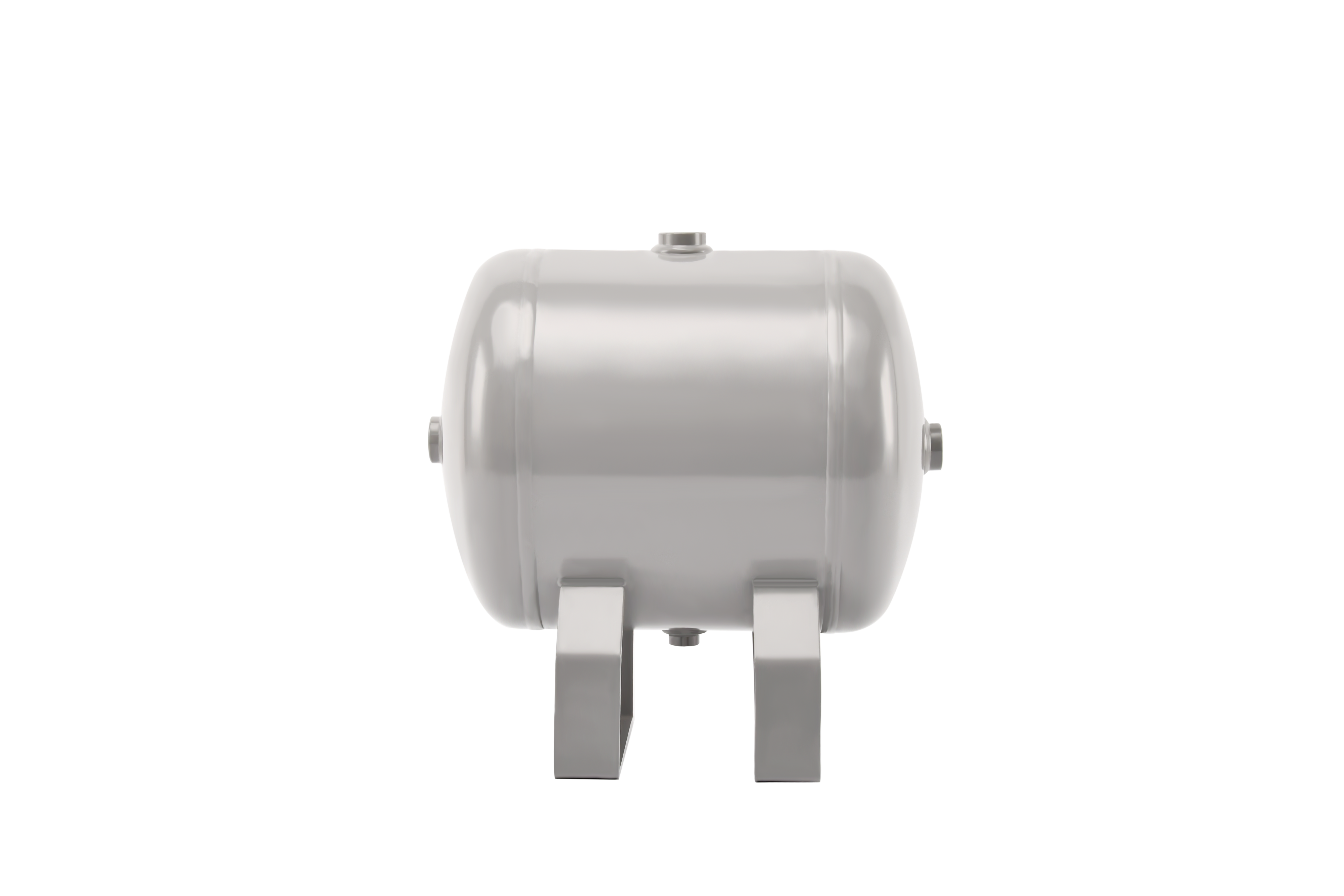
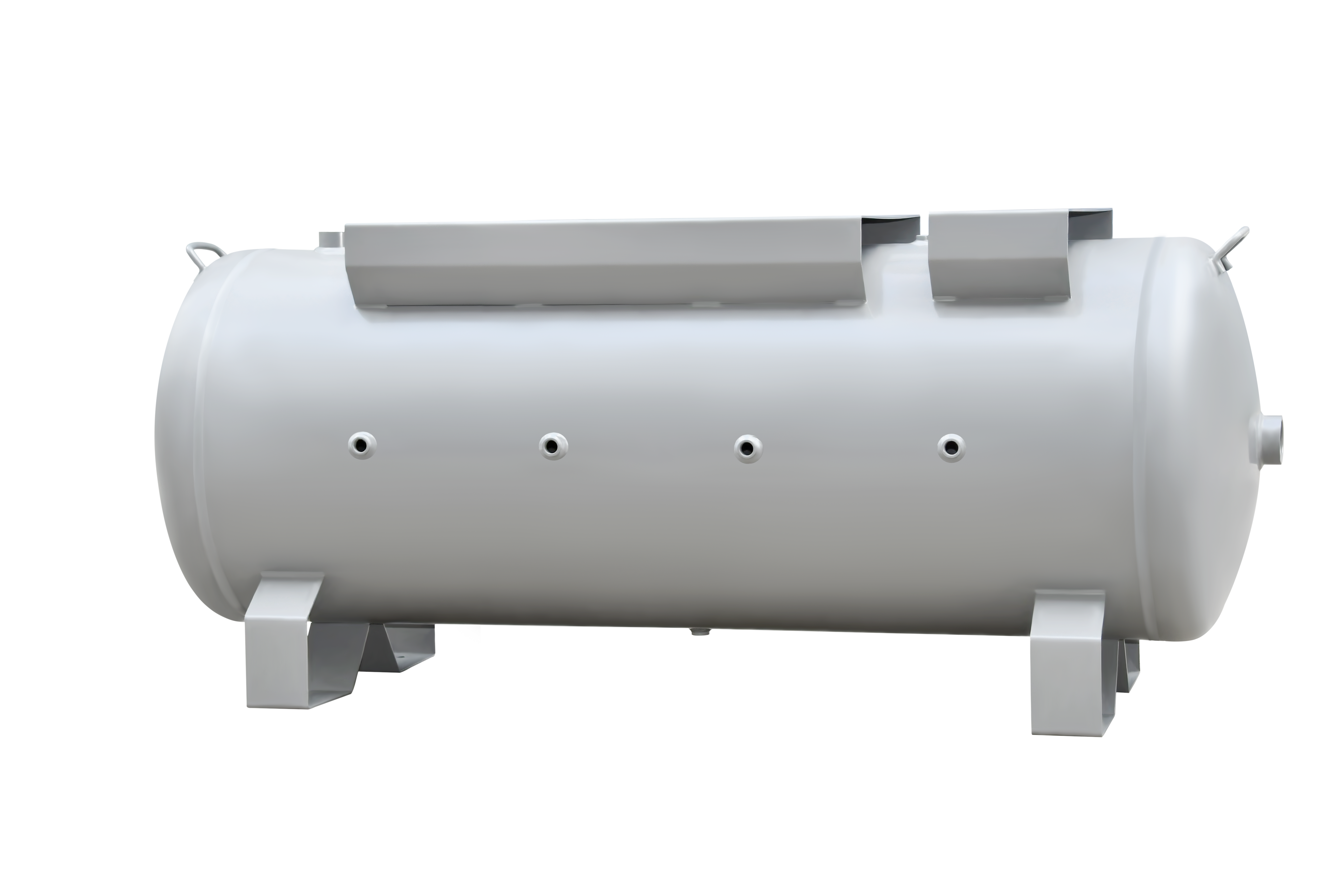
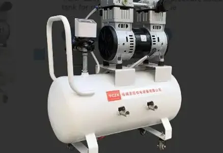
Hydrostatic testing represents one of the most critical final safety‑verification gates for finished industrial and custom‑built pressure vessels. This liquid‑pressure test subjects fully‑manufactured air receivers to elevated internal water pressure, verifying overall structural integrity, weld‑joint tightness, and the mechanical strength of shells, nozzles and connection interfaces. Unlike pneumatic air‑pressure testing, water‑based hydrostatic testing uses incompressible fluid, greatly lowering stored‑energy hazards during the test cycle, and reliably reveals hidden risks including micro‑cracks, pin‑hole leaks, insufficient weld penetration and sealing‑surface defects that visual inspection cannot detect.
For custom‑specification pressure vessels with unique port layouts and special test‑pressure requirements, strict standardized operating discipline becomes even more essential. At YCZX, every air receiver undergoes complete documented hydrostatic testing before shipment. Our nine‑step standardized workflow covers hardware preparation, thread sealing, gauge installation, water filling, full air‑venting, controlled pressurization, pressure holding, gradual depressurization and proper drainage. Every operator follows formal work‑instructions and mandatory personal‑safety rules. This rigorous procedure complies with GB150, ASME Section VIII Div.1 and global pressure‑vessel safety standards, confirming each tank can withstand its rated working pressure and delivering safe, certified products for worldwide industrial‑sector customers.
Step 1: Match fastener bolts per drawing requirements
Operators first cross‑check technical drawings to select bolts, plugs and fittings with correct specification, thread size, quantity and length. Mixing bolts of different grades, dimensions or material types is strictly forbidden. Mismatched fasteners will cause thread galling, insufficient pre‑tension or joint leakage during pressurization, leading to test failure and potential safety hazards. For custom‑order tanks with non‑standard threaded openings, every fastener is individually verified against drawing data rather than selected from general‑purpose stock bins. Correct bolt preparation builds the mechanical foundation for reliable sealing across all test ports.
Step 2: Wrap PTFE (Teflon) tape for threaded connections
PTFE tape is wound clockwise for all matching screw plugs and sealing bolts, with approximately fifteen complete wraps along each thread profile. Operators squeeze and press the tape end firmly against threads after winding. Two key rules apply: tape must never be wrapped excessively thick, and reverse‑direction winding is prohibited. Over‑wound tape fragments may break off and enter the thread cavity, causing partial blockages or preventing full seating of sealing surfaces. Proper PTFE‑tape application creates reliable thread‑sealing performance without introducing foreign‑body risks inside the pressure‑vessel shell.
Step 3: Torque‑tighten sealing bolts and plugs
All tank openings are securely sealed off, while three critical ports remain reserved: the water‑filling inlet, pressure‑gauge port and top air‑vent opening. Operators use torque wrenches to apply steady, even tightening force for every sealing fastener. A full final check is performed to ensure no bolt or plug remains loose or missed. Uneven or incomplete tightening will produce unpredictable seepage once internal water pressure rises, interfering with leak‑judgment during the hold‑pressure phase.
Step 4: Install calibrated pressure gauge
PTFE tape is also wrapped around the pressure‑gauge thread. The pressure gauge is mounted vertically upward for clear, easy observation of dial readings during pressurization. After installation, operators shake the gauge gently to confirm it sits firmly without tilting or wobbling. A poorly secured gauge risks detachment under rising pressure, creating safety risks and distorting pressure‑reading accuracy. Reliable gauge installation guarantees real‑time, trustworthy pressure monitoring throughout the whole hydrostatic cycle.
Step 5: Fill tank with clean water and expel internal air
Clean fresh water is injected from the designated filling inlet, while the top vent opening stays fully open. The water pump runs at low speed for slow filling. Operators continuously watch the vent outlet. Filling continues until steady water flows out of the top vent completely free of air bubbles. During the filling process, operators patrol every sealed joint to spot early minor water seepage. Trapped air pockets inside the vessel are extremely dangerous: compressible air causes unstable pressure readings and raises stored‑energy hazards even in water‑filled hydrostatic testing. Complete air removal is non‑negotiable before moving to the pressurization phase.
Step 6: Close and lock air‑vent port
After observing stable bubble‑free water outflow for at least thirty seconds, operators close and securely lock the top vent plug to achieve complete sealing. Every sealing position is re‑inspected for dripping or seepage. Under no circumstances shall operators seal the vent while air still remains trapped within the cavity. Any residual air will invalidate subsequent pressure‑hold test results. This step marks the transition from filling preparation toward formal pressurization.
Step 7: Controlled pressurization and pressure‑holding
Operators activate the hydrostatic test pump and raise internal water pressure slowly while keeping constant eyes on the pressure‑gauge dial. Pressure shall strictly follow test‑pressure values specified on product drawings. In our standard procedure, pressure rises until the gauge reaches 3 MPa, then the system maintains this target test pressure for a full 5‑minute hold period. All on‑site personnel must wear safety helmets during the pressurization and holding cycle. During hold‑pressure time, operators conduct comprehensive visual inspection of weld seams, nozzles and every sealed joint for water seepage, bead sweating or structural deformation. Any leakage or visible distortion marks the unit as failed and triggers depressurization for repair work.
Step 8: Gradual controlled depressurization after passing hold test
When the pressure‑holding inspection confirms zero leakage and zero deformation, operators slowly release internal pressure by turning the red relief‑valve handle counter‑clockwise. Rapid, full‑opening of the relief valve is strictly prohibited. Sudden fast depressurization creates powerful hydraulic shock waves that can injure personnel and damage threaded ports and gauge assemblies. Safe, slow pressure reduction brings internal tank pressure gently back toward ambient atmospheric conditions.
Step 9: Drain residual water safely
Only after confirming internal pressure has dropped fully to zero may operators proceed with draining. The relief valve is slightly opened to bleed any residual trapped pressure, then the bottom drain port is opened to empty all test water from the tank shell. Operators must never yank drain valves wide open; violent high‑speed water jets pose injury risks and may inflict mechanical damage on tank‑port threads and sealing faces. Complete draining prepares the pressure vessel for post‑test drying and downstream manufacturing workflows.
Hydrostatic testing goes far beyond a simple pass‑or‑fail check. Reliable test outcomes originate from disciplined pre‑test preparation, thorough air‑purging, gradual pressurization‑depressurization and strict on‑site safety management. Improper sealing, trapped air or reckless pressure‑handling will produce misleading test results and introduce workshop safety hazards that cannot be corrected after testing finishes.
YCZX refuses to rely merely on final‑test results to catch hidden flaws. We embed multi‑level quality‑check points across every phase of hydrostatic testing. This safety‑verification procedure sits at the late stage of our full manufacturing chain. It connects upstream plate‑rolling, welding, grinding and shot‑blasting processes and precedes final coating and pallet‑packaging. Together with incoming‑material inspection, non‑destructive examination and pneumatic leak checks, hydrostatic testing forms YCZX’s closed‑loop quality‑and‑safety management system for custom pressure vessels.
By enforcing documented hydrostatic‑test protocols and rigorous on‑site safety discipline, YCZX verifies weld integrity, joint sealing performance and overall structural strength for every finished air receiver. For global industrial partners working in machinery, compressed‑air stations, mining equipment and general‑manufacturing fields, YCZX delivers thoroughly‑validated pressure‑vessel products that satisfy international safety codes and ensure dependable long‑term field‑operation safety.