Ask five suppliers for a receiver and you will be offered five differently named objects: buffer tank, surge vessel, accumulator, separator, air receiver. In a compressed air system they are not interchangeable, and the label on the quotation often tells you more about the seller's vocabulary than about the vessel's function. Getting the pressure vessel types right at the specification stage is cheaper than discovering the mismatch during commissioning, when a vessel sized for storage duty turns out to be doing separation duty badly. This article sorts the common types by what they actually do in the system, then by orientation, then by pressure class, and ends with the selection logic that connects the two.
One caveat before the taxonomy: names drift. European drawings often call a receiver a "pressure tank", North American ones call a separator a "trap", and hydraulic suppliers use "accumulator" for a vessel that a pneumatics supplier would call a buffer. The function is the stable thing, so each type below is described by the job it performs, not by the word printed on it.
Main Pressure Vessel Types Used in Industry
Pressure vessel types are classified by function first - storage, separation, buffering or containment - because that function determines internal geometry, drain arrangement and the port schedule far more than the pressure rating does.
A vented, drainable shell holding compressed gas for later use is doing storage duty; a shell with a cyclone inlet and demister is doing separation duty; one tied into a closed water loop is doing buffering duty. Four families cover most of what industry buys.
1.Air receiver tanks
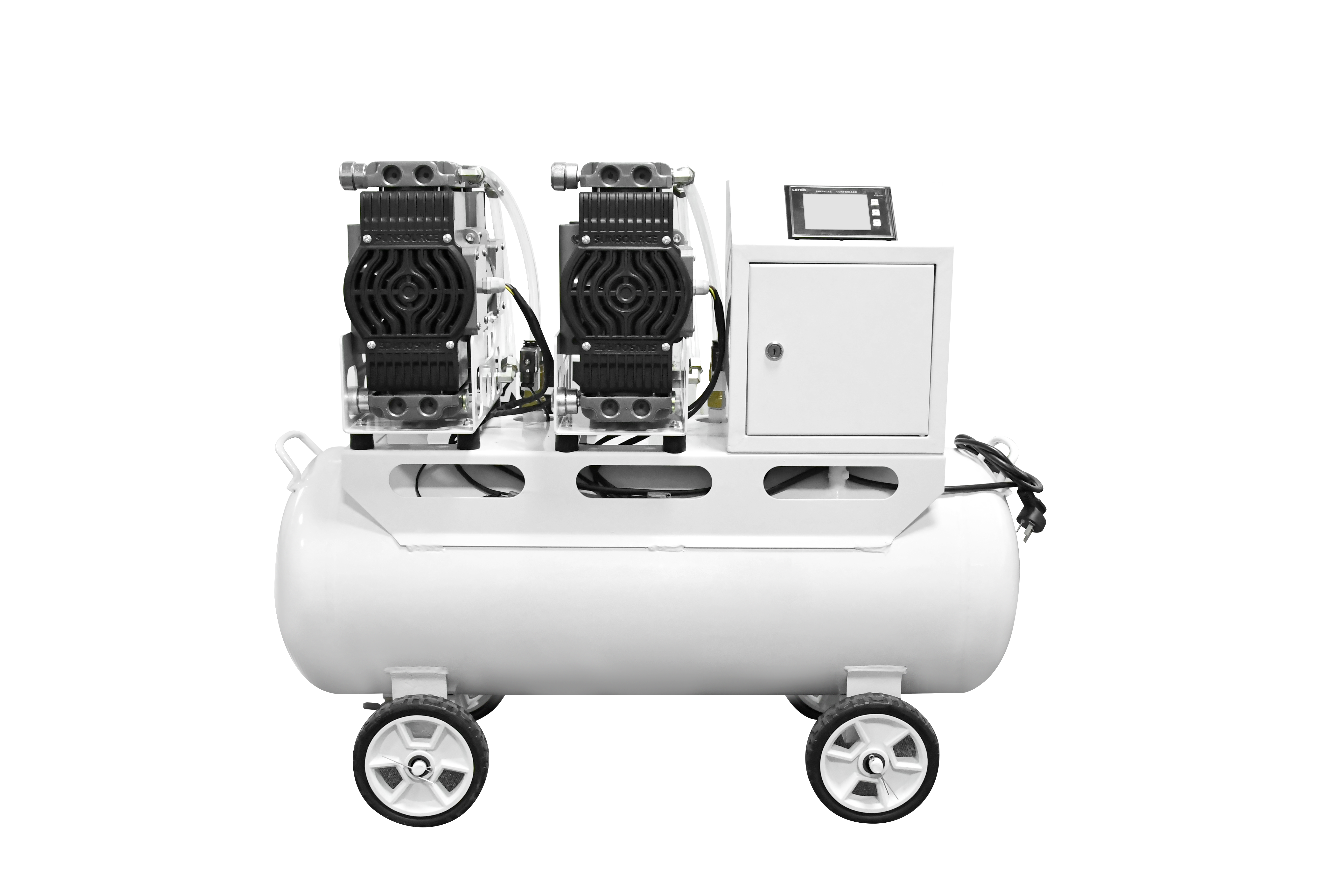
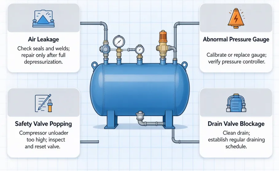
The workhorse of every compressor room. Air enters at the top or side, condensate collects at the bottom, and the volume absorbs the mismatch between a compressor that prefers to run at full load and tools that demand air in bursts. A receiver also cuts pulsation from reciprocating machines and gives the dryer a stable inlet. YCZX builds this family from 20 L to 10 m³ with carbon steel, stainless or aluminium shells, and the pressure vessel tank types in that range share the same drain-and-port logic rather than one catalogue shape scaled up and down.
2.Air and oil separators
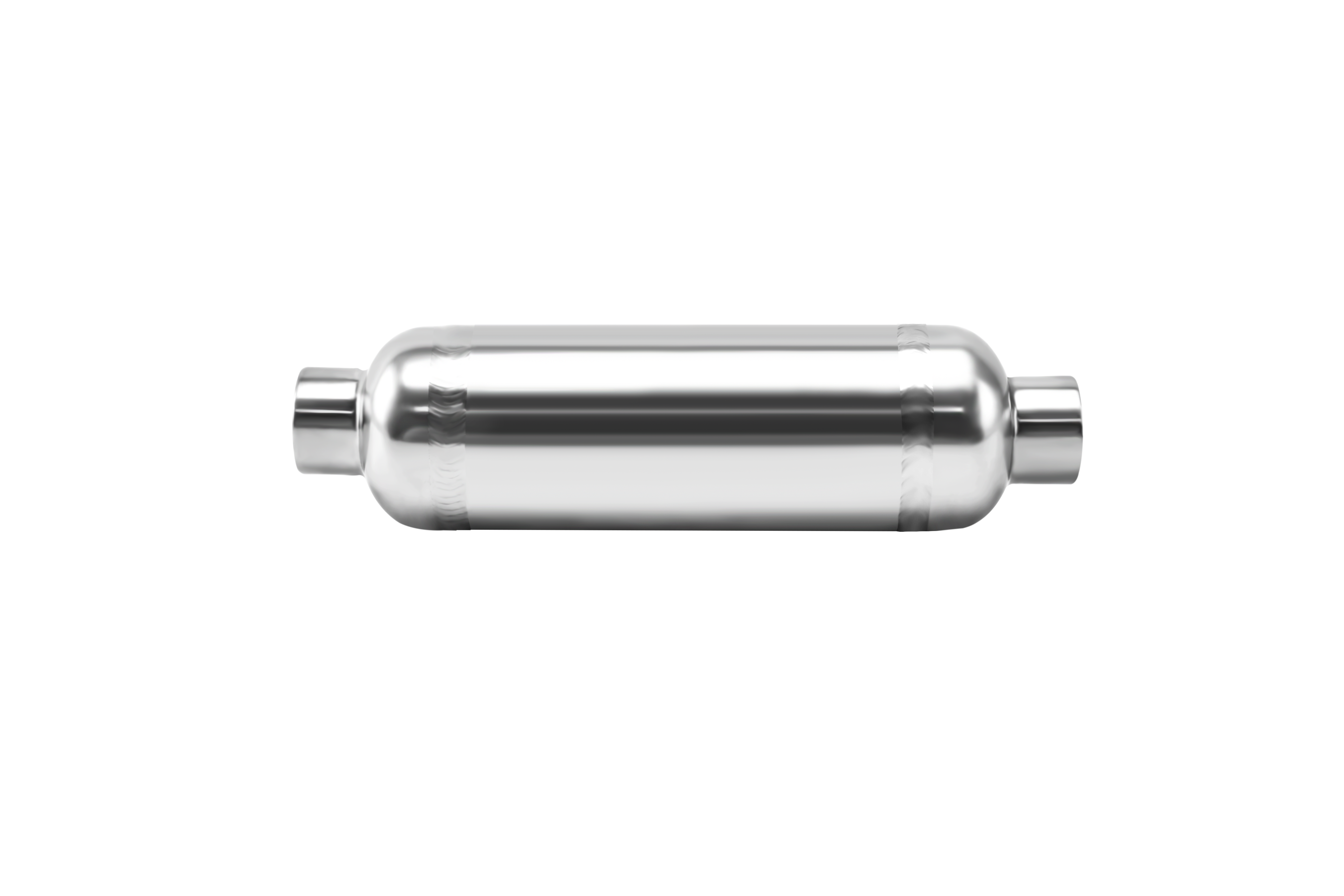
Downstream of an oil-injected compressor, the separator removes bulk oil aerosol before the air reaches a coalescing filter. It is a small vessel with a tangential or baffled inlet, a mesh or cyclone element, and a return line that feeds collected oil back to the sump. Oversizing costs little; undersizing sends oil into the dryer and shortens desiccant life.
3.Buffer and surge vessels
Buffers serve closed loops rather than gas. In hydronic heating and district energy the buffer decouples a heat pump or boiler from load swings, and in hydraulic systems the accumulator absorbs shock and stores energy. Same shell logic, completely different internals: a hydronic buffer wants stratification and low velocity, a hydraulic accumulator wants a bladder or piston.
4.High-pressure storage vessels
Breathing air banks, gas manifolds, test benches and laboratory supplies sit well above normal plant pressure, commonly 20 to 40 bar. These vessels are characterised by thick walls, seamless or forged construction, small volumes and a relief device sized for a fast fill rather than a slow leak.
Vertical and Horizontal Pressure Vessel Configurations
Vertical and horizontal pressure vessel configurations describe the same pressure boundary in two orientations. Among the different types of pressure vessels sold into compressed air systems, these two are separated by drainage, floor space, transport and nozzle access rather than by any difference in code compliance.
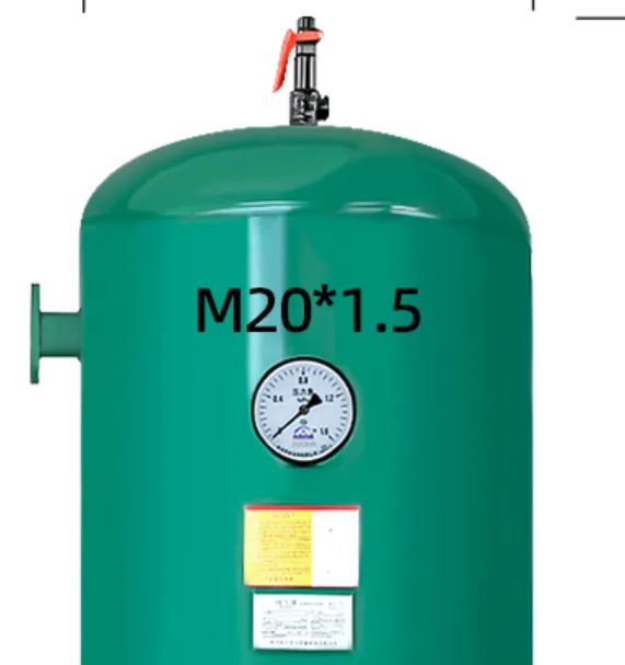
Vertical vessels put the drain at the lowest point of a single curved bottom, so condensate collection is unambiguous and a float or electronic drain works without a dip tube. They need headroom, which is why compressor rooms with low ceilings end up with horizontal units. Horizontal vessels win on volume per unit height, give generous side access for nozzles and instruments, and sit on saddles that allow thermal movement - but the drain has to be positioned at the low end and the shell often needs a slight fall to get water there.
| Criterion | Vertical configuration | Horizontal configuration |
|---|
| Floor space | Small footprint, tall silhouette | Large footprint, low silhouette |
| Condensate removal | Single bottom drain, no dip tube | Drain at low end, shell needs fall |
| Typical volume | 20 to 500 L | 200 L to 10 m³ |
| Installation | Manual handling, needs headroom | Crane or forklift, sits on saddles |
| Nozzle access | Top-mounted, tight working space | Side-mounted, easy instrument access |
| Best fit | Compressor rooms, tight footprints | Skids, trailers, low-clearance plants |
There is a service consequence buyers rarely price in. A vertical receiver with a bottom drain can be blown down during a shift handover; a horizontal one with a poorly placed drain traps a water layer that eventually reaches the dryer. Where maintenance staffing is thin, orientation is a reliability decision.
Receiver, Separator, and Buffer Vessel Designs
Receiver, separator and buffer designs differ inside the shell rather than outside it: a receiver is a still volume, a separator is a flow device whose inlet spins or deflects the stream, and a buffer is a low-velocity chamber coupled to a closed loop.
The receiver's only internal feature is usually a baffle or diffuser that keeps incoming air from stirring the condensate layer at the bottom; its performance is a function of volume. At 7 bar gauge a receiver holds roughly eight times the mass of air of the same volume at atmospheric pressure, so 1 m³ of storage is worth about 8 m³ of free air. A common starting rule is one gallon of receiver volume per CFM of compressor output, adjusted upward for bursty demand or for compressors cycling faster than ten starts per hour.
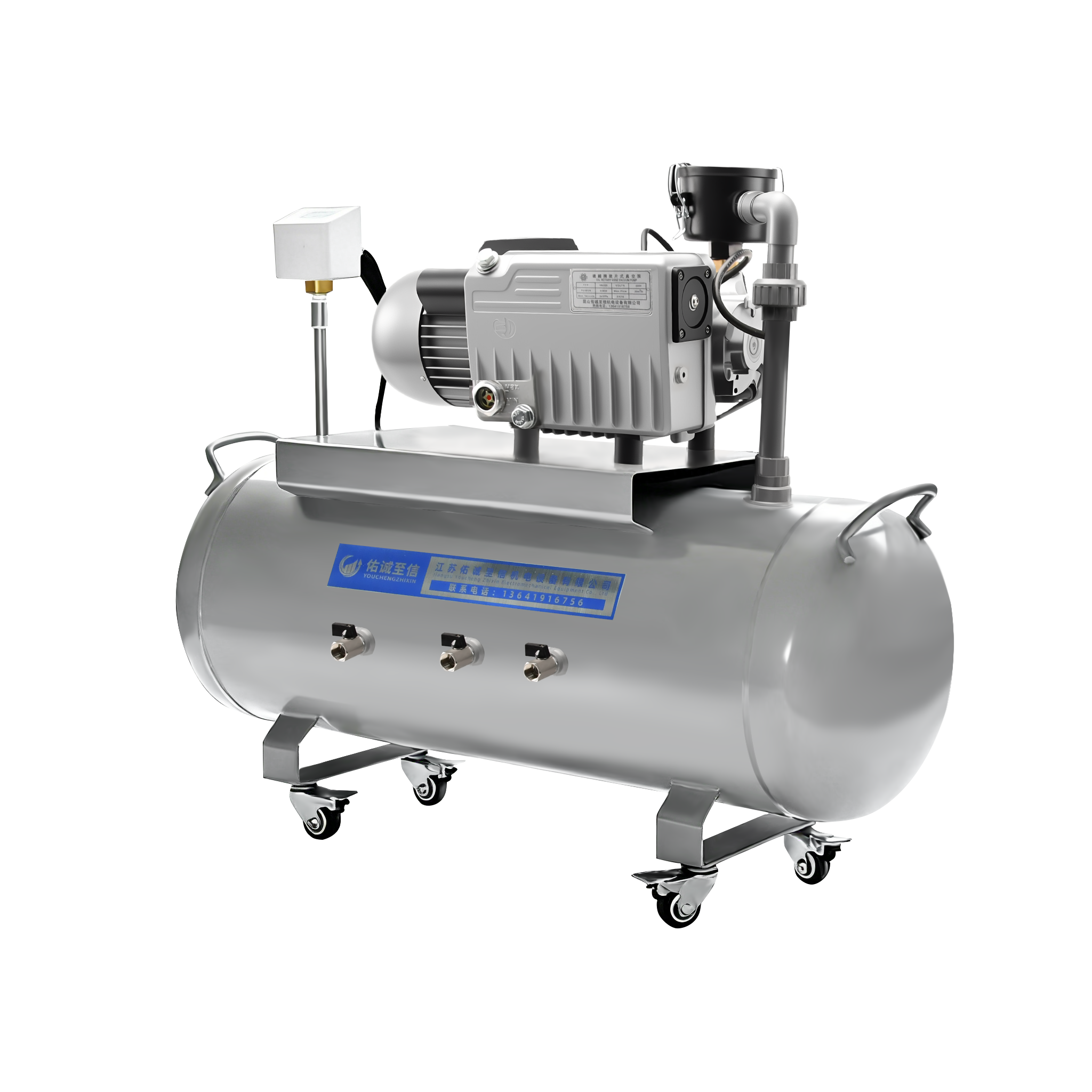
A separator is the opposite case: geometry does the work. A tangential inlet throws droplets to the wall, a demister or cyclone element catches the remainder, and a drain line returns collected oil to the compressor sump. Efficiency depends on inlet velocity, so a separator running far below its design flow separates badly even when it is clean. In vacuum systems the functional equivalent is the vacuum bucket or defoamer that protects a pump from liquid carry-over, and matching these small vessels with the right vacuum pumps is the difference between a stable vacuum level and a pump that trips on every process surge.
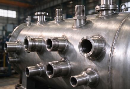
Buffers are designed around velocity rather than pressure. A hydronic buffer wants wide, slow, stratified flow so that hot supply sits above cool return; a hydraulic accumulator wants a bladder or piston that separates gas from oil. Treating either as an oversized receiver produces a vessel that holds water without doing any of the decoupling it was bought for.
Standard-Pressure vs High-Pressure Vessels
Standard-pressure and high-pressure vessels are separated by the wall-thickness regime they enter: standard units are rolled from plate in the 8 to 16 bar band, while high-pressure units move to thicker plate, seamless tube or forgings at 20 bar and above.
The commercial ratings in a compressed air catalogue are usually 8, 10, 13 and 16 bar, matching common compressor discharge pressures plus a margin. As pressure climbs, wall thickness rises roughly in proportion, head geometry shifts from torispherical toward hemispherical, and the examination regime tightens because stored energy grows with pressure and volume together. A 20 bar vessel is not a 10 bar vessel with a thicker wall; nozzle reinforcement, weld detail and relief sizing all change.Above roughly 20 bar the manufacturing route itself often changes. Small high-pressure vessels are frequently made from seamless tube with formed or forged ends rather than from rolled plate with longitudinal welds, which removes a weld seam and an inspection step. YCZX builds standard receivers in volume and takes custom high-pressure units up to 10 MPa in stainless and carbon steel, and the practical difference on a purchase order is usually not the shell but the number of witness points the buyer has to attend.
How to Select Pressure Vessel Types by Application
Selecting a pressure vessel type means matching four variables - duty, volume, pressure class and certification market - then accepting the orientation the available space allows.Work through it as a sequence of conditions. A vessel between compressor and dryer whose job is holding air is a receiver, sized from compressor output and acceptable cycle frequency. A vessel directly after an oil-injected compressor whose job is keeping oil out of the train is a separator, sized from inlet flow rather than storage need. A vessel tied into a closed water loop is a buffer, and the design question becomes stratification or bladder type. Above about 20 bar the type is still a receiver or storage bank, but construction route and relief sizing change.
Certification market is the fourth variable and it is usually the one that reshapes the quotation. A vessel with a pressure-volume product that puts it in a higher Pressure Equipment Directive category needs a notified body in the loop, and a North American installation needs an ASME stamp with a CRN registration if the unit also serves Canada. Where a booster is involved, the vessel and the pressure booster system should be specified together, because the booster's cycling behaviour sets the storage volume that makes it stable.
The cheapest mistake here is buying by volume alone: two receivers of identical size, one rated 10 bar and one 16 bar, differ in wall thickness, head cost and test regime, and only one suits a compressor that trips at 12 bar on a warm afternoon.
FAQs About Pressure Vessel Types
1.What is the most common pressure vessel type in a compressed air system?
The air receiver. Nearly every industrial compressor installation includes one, often as the only vessel on site, and it performs both storage and pulsation damping duty.
2.Is a buffer tank the same as a receiver?
Only in shape. A receiver stores compressed gas; a buffer decouples a closed liquid loop or absorbs hydraulic shock. Internals, port arrangement and sizing rules differ even when the shells look alike.
3.Do I need a separator if I already have a receiver?
Usually yes if the compressor is oil-injected. A receiver collects condensate by gravity but does not remove oil aerosol, and that aerosol is what loads the coalescing filter and the desiccant dryer.
4.Vertical or horizontal - which lasts longer?
Neither inherently. Vertical units drain more reliably, horizontal ones are easier to service, and the longer-lived choice is the orientation that matches the maintenance routine actually performed on site.
5.What pressure rating should a standard workshop receiver have?
Match the rating to the compressor's maximum discharge plus margin, which for most workshops means a 10 or 13 bar vessel on a compressor cutting out around 8 bar.
6.How many pressure vessel types can one compressor room need?
Typically two to four: a receiver, an oil separator, sometimes a buffer for a booster, and a small high-pressure bank for breathing air or test gas.
Conclusion
The useful way to read a quotation is to ignore the noun and ask what the vessel does. Storage, separation, buffering and containment each demand different internals, different port schedules and often different pressure classes, and the orientation then follows from headroom, drainage and service access. Send the duty, flow, pressure and destination market to YCZX and the pressure vessel type recommendation comes back with a drawing attached.
References